Purpose
This note discusses a simple nonlinear model of a linear-travel two chamber hydraulic actuator of a type most useful for position control applications. This model is derived from first principles in an intuitive fashion. An advantage of this nonlinear model, rather than a slightly simpler linear form more often seen, is that the nonlinear model incorporates limits of motion naturally near the ends of piston travel.
Pressure, Mass and Volume
Suppose that a specified pressure is maintained in a chamber. Under this condition, the volume needed to contain the fluid will correspond directly to the amount of fluid mass, all the way down to zero.
Suppose instead that a fixed fluid mass is maintained. Unlike a gas that would expand to infinity in a vacuum, a fluid would maintain a limited volume (ignoring the fact that it would attempt to become a gas, and in that manner expand to infinity). Within a wide range of pressures, volume decreases slightly at higher pressures and increases slightly at lower pressures.
These behaviors can be reasonably approximated by the following relationship.
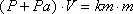
Combining these observations, we can postulate a model for the relationships between changes in pressure, mass and volume,

where the constants Pa and km calibrate to match observed operating conditions and physical properties. The positive term Pa forces the expression to be less sensitive to changes in pressure, and the term km adjusts for the density of the fluid.
A Two-Chamber Actuator
A hydraulic actuator typically operates on pressure difference, with a pressure pump supplying high-pressure fluid as an energy source, and with low pressure fluid drained to a fluid reservoir tank for recirculation. The actuator operates at approximately halfway between the high pressure source and return pressure, for example, 1500 psi.
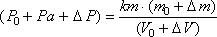
Let us consider deviations of pressure relative to the typical operating pressure Po (e.g. 1500 psi), with an actuator piston at mid-stroke. In this position, half of the piston volume appears on each side of the piston. This volume V can be expressed as A·L/2, where L is the total length of travel and A is the effective area of the piston. At this operating pressure and with these volumes, the amount of fluid that must be present in each chamber is mo.
An equivalent relationship is
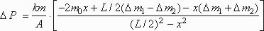
The force applied to the piston is determined by the difference of pressure on its two sides. We apply the relationship above to each side, and then take the difference. When we do this, the absolute and operating pressure terms cancel.
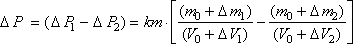
The volume of the cylinder is related to the piston effective area and the travel distance. Travel is relative to displacement from center of range, so

Factoring out the common piston area term yields
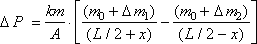
or after combining terms,
Common Mode Injection
Now we make the following assumptions:
The flow out of one chamber and the flow into the other will be very close to the same. Consequently, the two mass injection terms sum to approximately zero.
This residual represents common mode flow of material into or out of both chambers simultaneously.
The effects of common mode flow are small, uncontrollable and unobservable without special instrumentation. They have negligible effect on the external loading that we want to control. All we can do, or need to do, is let the pressures self-correct. Consequently, there is little point in trying to model this phoneomenon.
On the basis of these assumptions, retain only the dominant terms, and represent the differential material injection by a single mass transfer variable.
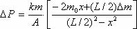
If we define the following notations
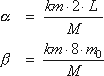
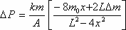
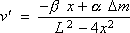
then we get a nonlinear compression model in the form
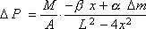
If this pressure difference is applied to effective piston area A to accelerate a mass M, the resulting acceleration is
This approximate pressure law can now be used to model the actuator device and its controls. The most important features of this expression are:
- opposing differential force as the piston moves,
- increasing differential force as fluid mass is injected,
- obtain linear approximation for small displacements x by ignoring the x2 term in the denominator,
- the denominator singularity prevents displacements from exceeding the travel limits at +L/2 and ‑L/2.